![]()
![]()
![]()
Vega prime FAQ's ![]()
![]()
![]()
![]()
|
|
|
Vega prime FAQ's |
|
|
![]()
|
| ||||||
|
| ||||||
| ||||||
|
| ||||||
|
| ||||||
|
Each Vega Prime window uses a frame buffer, which is a collection of bitplane's storing the information about each pixel. The organization of these bitplane's defines the quality of the rendered images and is known as a Pixel Format.
Pixel formats are made up from different Bitplane's which allocate for features such as:
Note that support for the various pixel format configurations and combinations are not uniform across different Windows Graphics cards, Linux Systems and Irix systems. Vega will ask the system for a bitplane specification supplied through the Lynx Windows panel settings or through code, the request may not be granted. When the notification level (in Systems panel) is set to Info or higher, messages tell the user which bitplane configuration is actually being used There are two methods of specifying bitplane configuration Vega. On Irix you can use findvis on the command line to display the available bitplane configurations supported on the Irix system On Windows you can use a program from nVidia to show the available bitplane configurations http://developer.nvidia.com/object/nvpixelformat.html Color RGB Alpha Depth Buffer Z Bits Samples Stencil Accumulation
| ||||||
|
Basically the idea behind LOD processing is that objects which are barely visible don’t require a great amount of detail to be shown in order to be recognizable. Object are typically barely visible either because they are located a great distance from the eye point or because atmospheric conditions are obscuring visibility. Both atmospheric effects and the visual effect of perspective minimize the importance of objects at ever increasing ranges from the current observers eye point. The effect is that the perspective foreshortening of objects, which makes them appear to shrink in size as they recede into the distance. To improve performance and to save rendering time, objects that are visually less important in a frame can be rendered with less detail. The LOD approach optimizes the display of complex objects by constructing a number of progressively simpler versions of an object and selecting one of them for display as a function of range. An undesirable effect called popping occurs when the sudden transition from one LOD to the next LOD is visually noticeable. To remedy this SGI graphics
platforms offer a feature known as Fade Level of Detail that smoothes the
transition between LOD's by allowing two adjacent levels of detail to be
sub-sample blended. This is now supported by most Scenegraphs, as long as there
graphics support multi-sampling Here's a link to a Practical overview of an LOD
| ||||||
|
For the symmetric frustum, both these planes are perpendicular to the line of sight of the viewer. The horizontal and vertical FOV's (fields of view) determine the radial extent of the view into the scene. FOV's are entered as degrees for the full width of the view desired. Entering a -1 for either but not both FOV causes the system to aspect match that FOV axis. For
example suppose the horizontal FOV is 45 degrees and the vertical is
set to -1. Once the window and channel are sized, the system selects
the appropriate FOV degree for the vertical FOV to maintain an aspect
ratio equal to that of the channel viewport.
Symmetric frustum
Also see the following Viewing Frustum Overview Image
| ||||||
|
This type of perspective frustum requires six values to define it. Clicking on the Asymmetric Frustum option displays the six entry fields. The near and far values are the same as the symmetrical frustum. The left, right, bottom, and top values define the side planes of the frustum. They are the angle offset in degrees for the plane they represent. See vpChannel and the Vega Prime Programmers Guide for further details.
Asymmetric frustum
Also see the following Viewing Frustum Overview Image
| ||||||
|
The sides of the frustum are parallel to the line of sight of the viewer. The Near and Far distances define the near and far clipping planes. The Left, Right, Bottom, and Top values define the frustum side planes. These values bear a direct relationship to the scale of the object being viewed. See vpChannel and the Vega Prime Programmers Guide for further details. Also see the following Viewing Frustum Overview Image
| ||||||
|
Vega Prime supports DIS through its optional (extra cost) module DIS/HLA add-on module For further details on MultiGen-Paradigm's DIS support see the MultiGen-Paradigm DIS/HLA for Vega Prime Datasheet
| ||||||
|
Vega Prime supports DIS through its optional (extra cost) module DIS/HLA add-on module For further details on MultiGen-Paradigm's HLA support see the MultiGen-Paradigm DIS/HLA for Vega Prime Datasheet.
| ||||||
|
The availability of increasing computer power, causes the DoD to view integrated electronic battle spaces as a feasible and cost-effective method of performing these functions. One approach to creating an electronic battle space is the DIS effort. The chief objective of DIS is to create real-time, synthetic, virtual representations of warfare environments (DIS 92). These environments are accomplished by interconnecting separate, distributed computers, which are called component simulator nodes. Each node is usually a manned simulator of an individual military unit (tank, APC, etc.). DIS provides flexibility in its ability to reconfigure simulators as necessary to support particular missions or exercises. The DIS interoperability properties allow heterogeneous simulators to interact such that interactions are ``seamless' to the participants and allow a ``fair fight.'' This means that when an exercise uses simulators of dissimilar abilities, these dissimilarities do not affect the outcome of the exercise. To support simulator interconnection, DIS also defines standards that allow the various simulators to communicate over local and wide area networks. DIS is an extension of the concepts developed by the DARPA Simulation Networking (SIMNET) program. While SIMNET was a successful demonstration of homogenous simulation networking, it was recognized that a method for heterogeneous simulator networking was needed. A heterogeneous simulator network provides for the interaction of simulators developed by various contractors for disparate DoD organizations. HLA, Vega Prime DIS-HLA provides easy-to-use support for the Real-time Platform Reference Federation Object Model (RPR-FOM). This HLA object model was developed by an industry consortium to aid in the transition from DIS to HLA by encapsulating the features of DIS. This also facilitates an API that is protocol-independent for the vast majority of operations. The RPR-FOM defines interactions that correspond to DIS PDUs. They can be accessed by your Vega DIS-HLA application in similar fashion to PDUs, using protocol-independent code. Vega Prime DIS-HLA also provides routines to receive and easily decode object updates within HLA that correspond to EntityState PDUs in DIS, but are somewhat different in form For further details on MultiGen-Paradigm's DIS support see the MultiGen-Paradigm DIS/HLA for Vega Prime Datasheet
| ||||||
|
The HLA was developed under the leadership of the Defense Modeling and Simulation Office (DMSO) to support reuse and interoperability across the large numbers of different types of simulations developed and maintained by the DoD. The HLA Baseline Definition was completed on August 21, 1996. It was approved by the Under Secretary of Defense for Acquisition and Technology (USD(A&T)) as the standard technical architecture for all DoD simulations on September 10, 1996. The HLA was adopted as the Facility for Distributed Simulation Systems 1.0 by the Object Management Group (OMG) in November 1998 and updated in 2001 to reflect the changes resulting from commercial standardization of the specification under the IEEE. The HLA was approved as an open standard through the Institute of Electrical and Electronic Engineers (IEEE) - IEEE Standard 1516 - in September 2000. In November 2000 the Services and Joint Staff signed the HLA Memorandum of Agreement identifying the HLA as the preferred architecture for simulation interoperability within the DoD For further details on MultiGen-Paradigm's HLA support see the MultiGen-Paradigm DIS/HLA for Vega Prime Datasheet
| ||||||
|
For further information and Help on the Sensor product you need to contact the MultiGen-Paradigm support department directly and they will be able to discuss your questions and concerns directly, but note that MPI are also bound by the restrictions imposed by the US state department
| ||||||
|
Vega Prime IR Scene computes and displays quantitative infrared sensor images of any environment containing natural backgrounds, cultural features and dynamic objects. IR Scene operates on the same synthetic environments as Vega Prime and Vega Prime Radar to produce correlated out-the-window and infrared views. IR Scene provides realtime, physics-based, band-specific scene generation at wavelengths from the visible through the far infrared. IR Scene also supports dynamic changes in scene temperatures and diurnal effects. IR Scene computes the apparent radiance of a scene from the position and orientation of the observer, producing quantitative radiance values in each pixel in units of W/cm2/sr. The radiometric equation used by IR Scene contains terms for modeling reflected solar and lunar energy, reflected ambient skyshine energy, path emission, scattering and thermal emittance
Vega Prime IR Sensor brings the world of sensor effects to a whole new level. IR Sensor users can add realistic sensor effects to scenes generated with IR Sensor to match the characteristics of a wide range of sensors using vis-sim style graphics parameters or real-world analytic sensor parameters. With support for a comprehensive set of sensor effects, IR Sensor is ideal for simulating devices that operate in any of the wavelengths supported by Vega Prime IR Scene, including night vision goggles (NVGs), medium and long wave infrared devices.
Vega Prime Radar is an optional module designed specifically to provide mathematically accurate, realtime 3D Radar displays to any Vega Prime application. VP Radar operates on the same synthetic environment as Vega Prime and Vega Prime IR Scene to provide fully correlated out the window, IR and Radar displays. VP Radar users can achieve optimal realism and performance across a number of Radar imaging modes including RBGM, DBS, SAR, and ISAR, including access to the functionality
The Texture Material Mapper or TMM is an optional tool that provides the ability to material-classify all of the textures in a visual/IR database. Just as color textures add realism to the simulated visual world, TMM is designed to help add detail and realism to the simulated sensor scene. The materials themselves are contained in a user-extensible database and include descriptions in terms of wavelength-dependent reflectance, heat-transfer and radar properties. Both Vega Prime IR Scene and Vega Prime Radar use these material-classified textures to determine the material properties of the visual database. TMM can classify individual texels with composite materials comprised of up to three individual materials at user-defined ratios to generate accurate classifications. The Smart create feature can be used to perform automated classification of a texture when provided with a set of user-specified training texels ( Important Note: Sensor tools and Modules are ITAR controlled so may not be available to every one, you will have to check with MPI)
| ||||||
|
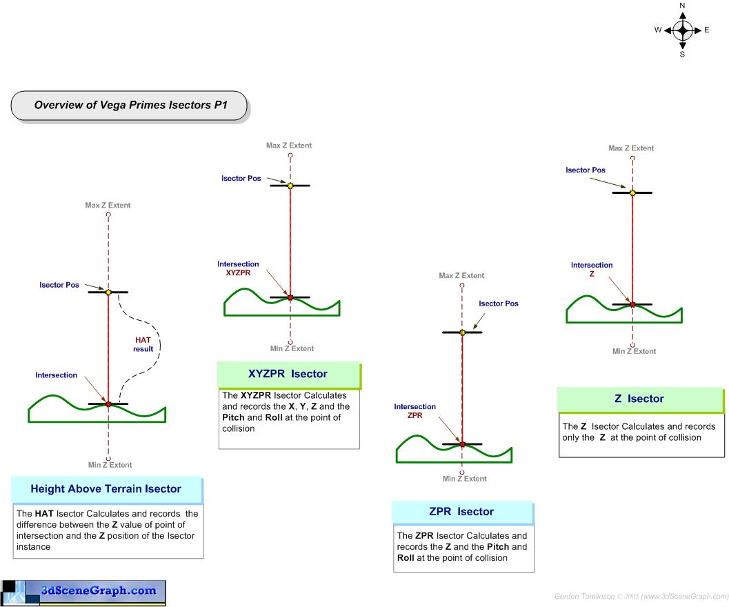
For example, a typical need is to obtain the current Height Above Terrain (HAT) information in a flight simulator or a driving simulator is determined by firing a vertical line segment from the aircraft or vehicle towards the terrain/ground and calculating the distance between the aircraft or vehicle and the intersection point on the ground. Line segments are used for intersection tests which are maintained and managed by vsIsector class. This is the base class for all isectors within Vega Prime which provides a data structure and a set of functions for the intersection result queries. In order to find out what a line segment may have hit, the scene graph has to be traversed node by node. The scene graph traversal is handled by vsTraversalIsect; the node level intersection test is done by each node; different types of node may require different intersection procedures. The vpIsector provides higher level API to configure the vsIsectors and query the result. The vpIsector derived classes shipped with Vega Prime represent different types of isectors which are frequently used in a visual simulation application, such as: vpIsectorLOS isector (See Image for Details) vpIsectorTripod isector (See Image for Details) vpIsectorBump isector (See Image for Details) vpIsectorZ isector (See Image for Details) vpIsectorZPR isector (See Image for Details) vpIsectorXYZPR isector (See Image for Details) vpIsectorHAT Isector (See Image for Details)
| ||||||
|
A line segment in this case is defined by 2 XYZ vectors a Begin and an End position. A vpIsector class such as vpIsectorLOS will position and orientate the line segment. Basically speaking the Isector will traverse its target scene graph and test a nodes bounding spheres against the Line segments. If no intersection is found then the node and all the nodes children are a rejected, this allows for fast collision detection. If an intersection hit is encountered with the bounding sphere the test can them become more fine grained test of each child node for an intersection until the leaf geometry node is reached, then data on the collisions detected can be stored such as pointers to node, position of intersection, the normal perpendicular to the intersection etc. (This is of course an oversimplification of a more complicated process)
| ||||||
|
The 'Z' isector defines an internal single line segment. This line segment extends from Z = maximum terrain elevation to the Z = minimum terrain elevation at the current X,Y position of the Isector. The output of this method is the Z value of the highest intersection point at the current X,Y position. When the 'Z' isector is used with a flat earth coordinate systems, the Z coordinate is the value of the point of intersection with the terrain. When using a non flat earth coordinate systems, the user should use a 'HAT' or 'XYZPR' isector method instead of Z to compute elevations as elevation is then a function of x,y,z. See vpIsectorZ help page and Vega Programmers Guide for further details on Isectors
| ||||||
|
The pitch and roll values returned by the intersection depend upon the current heading of the isector. The normal of the primitive intersected, along with the isector heading, provides all the information required to determine the orientation at the point of intersection. When used with a flat earth coordinate systems, the elevation computed is equivalent to the Z coordinate value of the point of intersection with the terrain. When using non flat earth coordinate systems, use the HAT or XYZPR methods instead of ZPR to compute elevation. See vpIsectorZPR help page and Vega Programmers Guide for further details on Isectors
| ||||||
|
The 'HAT' (vpIsectorHAT) is a type of isector provided by Vega Prime, which can be used to compute height above terrain. When used with a flat earth coordinate systems, this is equivalent to the difference between the current Z coordinate value of the isector minus the Z coordinate value of the point of intersection with the terrain. When used with a non flat earth coordinate systems, the HAT is equivalent to the Euclidean distance between the current location of the isector and the point of intersection. Regardless of the coordinate system type used, a positive value for HAT indicates that the isector position is above the terrain surface. A negative value indicates that the isector position is below the terrain surface. Zero means that the isector is "grounded". See vpIsectorHAT help page and Vega Programmers Guide for further details on Isectors
| ||||||
|
Three line segments are used to compute intersection points with the terrain. The intersection points, one per line segment, define a plane. Using the current value of heading for the isector position, and the normal to the generated plane, the TRIPOD isector method computes three values, the Z coordinate which is the tripods center, pitch in degrees, and roll in degrees. See vpIsectorTripod help page and Vega Programmers Guide for further details on Isectors
| ||||||
|
The 'LOS' (vpIsectorLOS) is a type of isector provided by Vega Prime, which can be used to compute "Line Of Sight ranges". For example, a LOS isector can be used to implement a laser range finder, or to decide if point B is visible from point A, and, if not, what is in the way. See vpIsectorLOS help page and Vega Programmers Guide for further details on Isectors
| ||||||
|
The Bump Isector is surprisingly effective. It is based on the idea of "curb feelers". The length of the line-segments are controlled by the three properties Width, Length, Height which correspond to the line-segments for the x, y, and z body axes respectively. The reason that there are six line segments in this isector, instead of just three, is that the line segments have direction as well as length. Primitive surfaces, such as tri's, quads, or tmeshes that are back facing with respect to the direction of the line segment are ignored. This is done to make the intersection tests more efficient. If your database does not take advantage of backface removal you could possibly reduce your drawing time and intersection time a considerable amount by redesigning your database to utilize backfacing. See vpIsectorBump help page and Vega Programmers Guide for further details on Isectors
| ||||||
|
The 'XYZPR ' (vpIsectorXYZPR) is a type of isector provided by Vega Prime, which can be used with a non flat earth coordinate systems to compute the point of intersection as well as the pitch and roll at that point. This isector uses the current heading of the isector to calculate pitch and roll values from the normal vector of the intersected primitive. The pitch and roll values returned depend upon the current heading of the isector . The normal of the primitive, along with the isector heading, provides all the information required to determine the orientation at the point of intersection. See vpIsectorXYZPR help page and Vega Programmers Guide for further details on Isectors
| ||||||
|
| ||||||
|
| ||||||
|
Note at load time additional processing is also done to generate mipmaps, scale images, and convert them into powers of two which most graphics cards require. For other texture formats you must either convert them to one of the above formats or provide your own texture loader Note : I have noticed that the documentation may be out of date and has not been update with Vega prime 2.0 on the formats it current supports
| ||||||
|
Vega Prime 1.x does not support the TIFF image format directly, you will have to either convert the image to a support format (See FAQ 72 and FAQ 71) or alternatively provide you own TIFF texture loader
| ||||||
|
Not Supported in Vega Prime 1.2 Note : I have noticed that the documentation may be out of date and has not been update with Vega prime 2.0 on the formats it current supports, so check with MPI support if you need to
| ||||||
|
You cannot use the OpenFlight API in Vega Prime to modify an vpObject that has been loaded in to memory by Vega prime, in fact your cannot use the API directly on Vega Prime Instances. You could use the OpenFlight API to modify an OpenFlight file base on some event, where you load the OpenFlight file using the API, modify the files, then save the file and then you could use Vega Prime to load the saved and modified files. You could possibly create an OpenFlight converter using the API as well. Also note you will need to ensure you have the correct licenses from MPI if you are going to distribute your application that use the OpenFlight API.
| ||||||
|
There have been rumours that Vega Prime may get a loader but as yet there is no sign of this publicly or acknowledgement from MPI if there is going to be such a loader, also at some point Terrex were possibly going to provide a loader but again this has never been seen or acknowledged publicly Right now you have to publish you Terra Page data base in OpenFlight format
| ||||||
|
If a Vega or Vega Prime based application is running in locked phase, the drawing process will swap buffers only on frame boundaries. A benefit of locking is that such pipelines are self regulating so synchronizing two Pipes together is simple, even across different machines. Another benefit is that latency is minimized and predictable. The major drawback is that if a channel takes slightly longer than a frame to render (it has 'frame-extended'), then an entire frame is skipped rather than a single vertical retrace period. However, if minimal distraction is crucial, the phase can float so that buffer swapping may happen on non-frame boundaries. In this case it is not guaranteed that the windows on pfPipes will swap together; they may get out of phase resulting in inconsistent images if the displays are adjacent and are displaying the same scene. The difference between locking and floating becomes less apparent with increasing frame rates. At a rate equal to the vertical retrace rate, there is no difference. Also, if the pipes do not actually 'frame extend', then there is no difference. Applications which do not require a fixed frame rate may use Free Run or Limit. Free Run essentially disables the fixed frame rate mechanisms and will cause the application to run at its rendering rate so it slows down when rendering complex scenes and speeds up when rendering simple scenes. In this case, the frame rate specified by pfFrameRate no longer affects the system frame rate but is still used to compute system load and stress. Additionally, if the APP, CULL, or DRAW stages are in separate processes, they will run in lock step and each stage will wait for the downstream stage to get its results and likewise, downstream stages wait for upstream stages to finish. This is the desired mode if you need to be sure that every APP frame is actually drawn and that the APP can not spin ahead of the draw is slow and extends past its goal frame time. Limit is equivalent to Free Run except that the application can go no faster than the frame rate specified by setting the desired Frame Rate although it may go slower. Thus fixed frame rate behaviour is achieved if the time required to process a frame never takes longer than that specified by target Frame Rate.
| ||||||
|
The relationship between the machines allows for a 'Master' system and multiple 'Slave' systems within one configuration. The general defining requirement for the need of Distributed rendering is any application with a single input, and multiple contiguous or non-contiguous displays. Any Vega Prime application can be used with Distributing Rendering by the simple addition of a few settings in LynX Prime. Vega Prime Distributed Rendering includes tools that enable the simple setup and configuration of multiple channel applications. Users can easily enable multi-channel applications using A GUI interface that provides the ability to set up, test, manage and configure your applications on the hardware that will be used. Common activities managed by the Distributed Rendering Utilities include:
Distributed Rendering features include
| ||||||
|
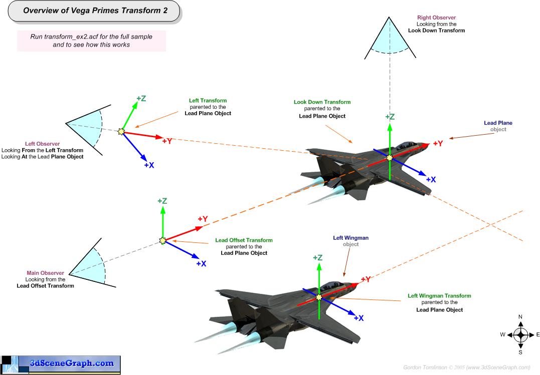
But not all is totally lost Vega Prime introduced a new Class called vpTransform, this class provides similar functionality to a vgPlayer, in that you can use it as a holder and offset, but offers a more powerful interface and functionality for the most part.
One of the better features of a vpTransform is that you can attach any type of node to the instance, see the vpTransform html help pages and Vega prime Programmers guide for more information
See this Example Image and Example AFC for details on a vpTransforms
| ||||||
|
SGI Monitors and graphics hardware uses a different setting for the Gamma output to that of a PC So normally a the PC textures will look very bright on SGI machines while a SGI texture will look very dark If we say that the SGI machines have a Gamma value of 1.0 then we can say the Windows PC's machines have a gamma value of around 1.7, this is typically the difference in gamma So the solution is to adjust your textures gamma/brightness either up or down depending on which system they are being used
| ||||||
|
| ||||||
|
See vpGeometryPageable::setGeometryFormat(..) and vrGeometryBase::Format Also Check out the advanced tab on the vpObject panel in Lynx Prime
| ||||||
|
Yes Vega Prime 2.0 now supports VBO's "Vertex buffer Objects",as long as your graphics hardware and driver supports the feature ( Requires Opengl 1.5 or higher support) . See vpGeometryPageable::setGeometryFormat(..) and vrGeometryBase::Format Also Check out the advanced tab on the vpObject panel in Lynx Prime
| ||||||
|
This feature providwes a mechanism of encapsulating data within 'Buffer Objects' for handling these data without having to take them out from the server side, thereby increasing the rate of data transfers. The basic idea of this VBO mechanism is to provide some chunks of memory (buffers) that will be available through identifiers. As with any display list or texture, you can bind such a buffer so that it becomes active. The binding operation turns every pointer in every client/state function into offsets, because we will work in a memory area that is relative to the current bound buffer. In other words, this extension turns a client/state function into a server/state function. We all know that a client/state function deals with data whose scope is only accessible for the client itself. Another client won’t be able to access any of this data. As a consequence of passing these functions on the server’s side, it is now possible to share this data between various clients. Many clients will be able to bind common buffers, and everything is dealt with just like texture or display list identifiers. ( Note that VBO's requires Opengl 1.5 or higher support)
| ||||||
|
| ||||||
|
One reason might be because when MultiGen Creator builds a terrain file it will apply it's real world coordinate positions which is then picked up by VegaPrime when the files is loaded What you can happen is that the user is initialising their observer at the default coordinate origin of 0,0,0 but the terrain is being read in and positioned thousands on miles/kilometres away What you can do correct this situation is to use MultiGen Creator to find the coordinates of the terrain and enter them as an the start position for the Observer in Lynx Prime Also you might be at the centre of your terrain but just under there terrain and as by default Vega Prime does not render back faces you will not see the terrain. You can again correct his in the same manner as above. Another problem might be that the scale of the terrain is wrong check the units you modelled are not say millimetres, as the default units for VegaPrime is Meters. Check that the file is actually being loaded, look in the console to see if there were any warning about not being able to load the file Check you have add the file to the scene, and if you are using Asynchronous page loading then it will not start to be loaded until you add the file to the scene Check you LOD settings are correct and that you close enough for them LOD to draw something
| ||||||
|
If you now the X and Y position that you want to find the Z then you can simply use a vpIsector such as vpIsectorZ or vpIsectorHAT isectorss. You would then simply position the vpIsector at the given X and Y coordinates, do the intersection test and retrieve the Z from the returned Hit results See the examples provide with Vega Prime several use isectors such as: $(MPI_LOCATE_VEGA_PRIME)\resources\samples\vegaprime\vpmotion\vpmotion_walk\vpmotion_walk.cpp $(MPI_LOCATE_VEGA_PRIME)\resources\samples\vegaprime\vppath\vppath_landing\vppath_landing.cpp
| ||||||
|
Several of the samples shipped though do use isectors such as $(MPI_LOCATE_VEGA_PRIME)\resources\samples\vegaprime\vpmotion\vpmotion_walk\vpmotion_walk.cpp $(MPI_LOCATE_VEGA_PRIME)\resources\samples\vegaprime\vppath\vppath_landing\vppath_landing.cpp If you need help with a specific type of isector, I would contact MPI support and ask for a sample ( at some point I will most likely add a set of samples to the code section)
| ||||||
|
Yes you can retrieve the current position of the Sun environment effect, this ability was added in Vega Prime 2.0 release The position of the Sun in geodetic coordinates ( latitude / longitude) can now be queried using vpEnvCelestial::getPosition(..) function The orientation and direction of the body relative to the observer's ENU coordinate system can be queried using vpEnvCelestial::getOrientation() and vpEnvCelestial::getDirection() functions Finally the radius and orbit of the body can also be queried with vpEnvCelestial::getRadius() and vpEnvCelestial::getOrbit()
| ||||||
|
The position of the Moon in geodetic coordinates ( latitude / longitude) can now be queried using vpEnvCelestial::getPosition(..) function The orientation and direction of the body relative to the observer's ENU coordinate system can be queried using vpEnvCelestial::getOrientation() and vpEnvCelestial::getDirection() functions Finally the radius and orbit of the body can also be queried with vpEnvCelestial::getRadius() and vpEnvCelestial::getOrbit()
| ||||||
|
You can use code along the lines of the sample below to find a named Switch node in a vpObect
Note in Vega Prime 2 the function findNamed(...) has been changed to find_named(....) | ||||||
|
With a vsSwitch Node the children to be rendered are contain in a mask which is simply a vuVector of integers, where each integer represents the location of a child in the children list of the node, Where 0 is the index of the first child, 1 is the index of the second child, etc... If a mask contains the non-zero values in elements 1, 4, and 5 of the vector, then children 1, 4, and 5 will be rendered. Typically a switch allows you to easier show different representation of a model, e.g with a tank, you can have a Normal State, Damaged state and Destroyed, the switch then allows you to render the require state
| ||||||
|
A Switch node mask is a powerful extension from Multigen-Paradigms, the original basic Switch nodes allowed the user through the API to draw either ALL the nodes children, None of the children or One of the Children. For example: if we have a switch node that has 4 nodes A B C D, we can draw [] or [ABCD] or [A]or [B] or [C] or [D], we can not have [AB] or [BC] with a basic switch node Switch masks add a Powerful features to switch nodes that allow a mask to be used to decide which of the children are to be drawn, so that combinations such as [AB] or [BC] or [ACD] can be used as well as None or All children. See the MultiGen Creator documentation and vsSwitch.h for further information
| ||||||
|
| ||||||
|
Unfortunately the environment Cloud/Sky effects in Vega Prime do not currently have a Slant deck like the Old hinged cloud did in Vega Classic
| ||||||
|
While this effect will give you the look of Snow falling, it will not chnage the appearnce of you terrain or database, you will need to model and alternative databse with textures that match a snowing environement etc.
| ||||||
|
While this effect will give you the look of rain falling, it will not chnage the appearnce of you terrain or database, you will need to model and alternative databse with textures that match a raining or water environement etc.
| ||||||
|
The vpEnvCloudVolume environment effect has built in effects for simulation a storm cell, including a Rain Shaft and Lightning effect
Using the vpEnvCloudVolume along with is Rain Shaft and Lightning effects
in combination with the environment Fog, TOD day, lighting, vpEnvRain , add an
overcast cloud layer or layers, add in wind layers etc and you can simulate a
pretty good looking storm | ||||||
|
Vega Prime 2.0 does provide a Lightning effect for the environment but only as part of the vpEnvCloudVolume effect
| ||||||
|
If you require impostors then you will have to write your own implementation or use a 3rd party library
| ||||||
|
Vega Prime 2.0 currently doesn not offer direct support for Cube mapping. Of course you can imlpement your own code to do this in OpenGL or drawble etc ....
| ||||||
|
| ||||||
|
The Only way in Vega Prime is to set the node through code other then a vpObject's root node, as a vpObject's root node has its isector mask set through Lynx Prime and Code . Vega Prime does not have an Object Editor Tool as found in Vega Classic One coding approach might be to tag the nodes you want to set a mask on in your modeling package such as Creator. Such as using the Nodes Name or Comment field ( Creator ) and use a naming convention that would allow you to use a loader call-back or post load time to check a nodes name and if the tag matches then set the isector mask etc. Obviously this assumes you have access to a modeling package and can change names or set the comment fields etc ...
| ||||||
|
© Copyright 2005-2006 Gordon Tomlinson All Rights Reserved. All logos, trademarks and copyrights in this site are property of their respective owner. | ||||||
![]()


 IR Scene (
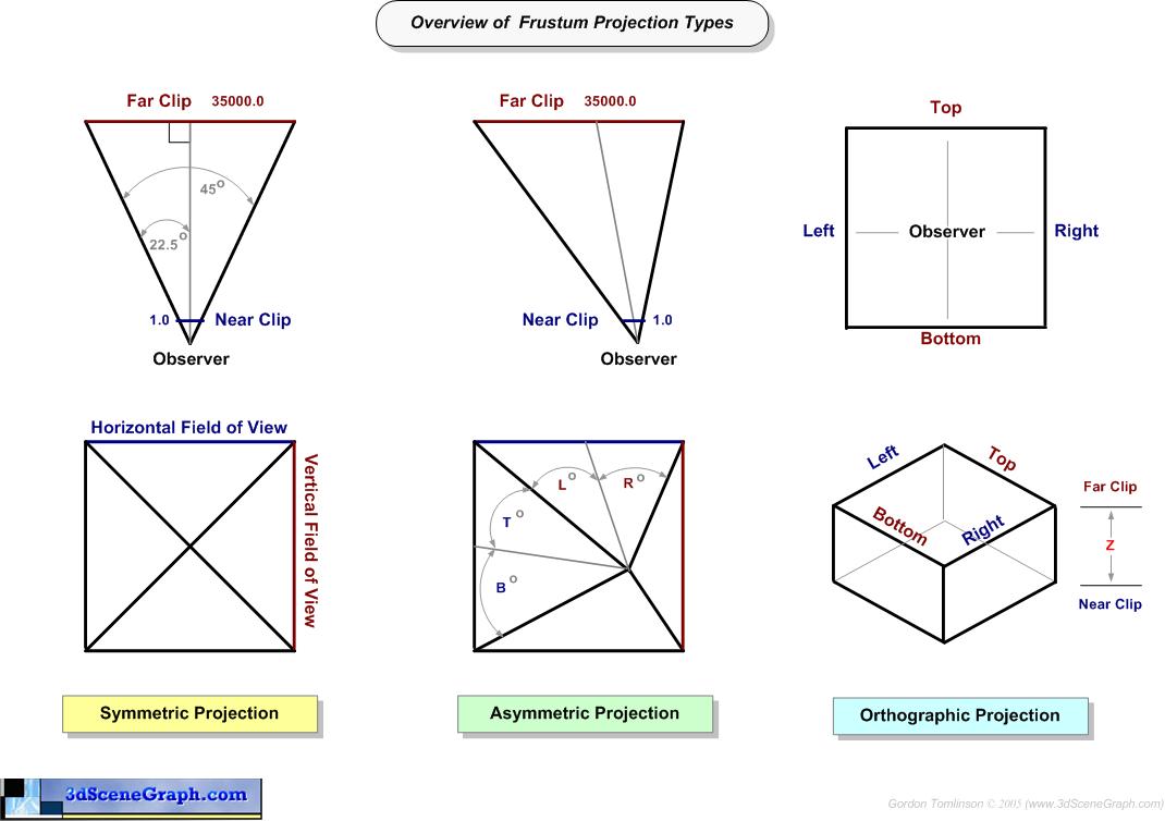